Portal Frame Steel Structure for Incubation Base

In the steel structure system, portal frame steel structures are widely applied in various building types such as single-story industrial plants, warehouses, trading markets, and public buildings. The Technical Specification for Portal Frame Steel Structures GB51022-2015, approved and issued by the China Construction Standardization Association, serves as a critical guideline for design and construction.
When selecting such steel structures, clients must first determine the primary structural form to establish the overall framework. Portal frame steel structures offer configurations such as single-span, multi-span, single-slope, double-slope, and options for crane inclusion. These structural variations primarily address functional requirements, load capacities, operational conditions (e.g., drainage, snow accumulation), and other practical needs.
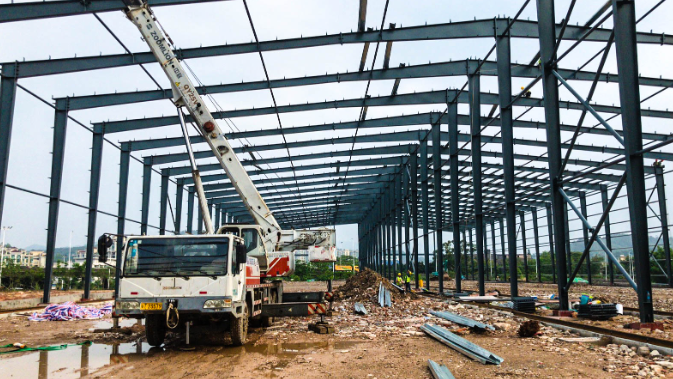
Modern portal frame steel structures typically utilize H-beams as the main structural material. Under vertical uniformly distributed loads, significant bending moments occur at the beam-column joints and mid-span of the portal frames. Horizontal loads also generate substantial moments at the frame corners, while other regions experience smaller moments. To optimize material efficiency, H-beams with variable cross-sections (larger at stress points, smaller elsewhere) are often employed instead of uniform cross-sections.
In this system, the primary structure bears the main loads, while the supporting system facilitates force transmission and stabilizes the beams and columns. These components are critical for ensuring installation safety and overall structural integrity. Key supporting elements include tie rods, corner braces, struts, longitudinal/lateral supports, and column bracing, which collectively enhance the structure’s rigidity. The supporting system transfers horizontal wind loads, seismic forces, crane braking forces, temperature-induced stresses, and other horizontal loads to the foundation, while ensuring lateral stability of beams and columns.

Column bracing (especially for crane-equipped lower column bracing) determines the direction of longitudinal deformation and temperature stress magnitude. It is typically positioned at mid-span or at one-third intervals along the longer axis, with spacing not exceeding 60 meters. For crane-equipped structures, lower column bracing may be omitted at the ends to minimize temperature stress. Roof lateral supports are aligned with column bracing to form a geometrically stable system.
The purlin system, attached to the primary structure, supports and secures roof and wall cladding. Purlins are typically composed of C/Z-shaped steel, struts, corner braces, and stay tubes, fabricated from cold-formed thin-walled steel, angles, round steel, or pipes. Connections are made via Grade C bolts or welding.
Purlin systems are categorized by location:
- Roof purlins: Account for panel weight, self-weight, suspended loads, wind/snow loads, and construction stresses.
- Wall purlins: Consider wall panel suspension, wind pressure/suction, and alignment with doors/windows and gutters. Purlin specifications and spacing are guided by the Cold-Formed Thin-Walled Steel Structural Design Code GB 50018-2002.
Due to the complexity of purlin system components, common construction issues include under-tensioned struts, loose bolts, and compromised stability, leading to potential structural risks. Proper section sizing, rational support connections, and meticulous maintenance are essential to ensure the system functions effectively.


